
The OSI model divides network communication into seven layers, from the physical transmission of bits to the application the user actually sees. Published by the ISO in 1984 as an international standard, its purpose is conceptual: it gives everyone a common vocabulary for describing where each technology operates and where a problem is occurring.
In practice, almost no network is implemented exactly to the OSI specification — the internet runs on TCP/IP. But OSI survived as the reference everyone uses to teach, diagnose and talk about networks, because it separates responsibilities that TCP/IP bundles together.
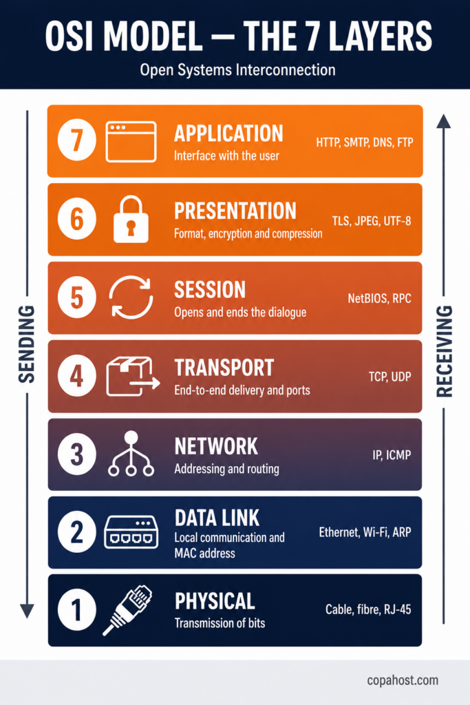
| 7 — Application | The interface with the user. HTTP, SMTP, DNS |
| 6 — Presentation | Format, encryption and compression. TLS, JPEG |
| 5 — Session | Opens, maintains and ends the dialogue |
| 4 — Transport | End-to-end delivery. TCP and UDP |
| 3 — Network | Addressing and routing. IP |
| 2 — Data Link | Communication between neighbours. MAC, Ethernet |
| 1 — Physical | The bits on the wire or in the air |
What is the OSI reference model?
OSI — short for Open Systems Interconnection — is a reference model describing how different systems communicate over a network, by dividing the process into seven independent layers.
The core idea is separation of responsibilities. Each layer does one thing, offers a service to the layer above, and consumes the service of the layer below — without needing to know how the others work internally. An application sending an email doesn’t need to know whether the connection is copper, fibre or Wi-Fi; that’s layer 1’s problem.
This organisation delivers three practical benefits:
- Interoperability. Equipment from different manufacturers works together, as long as each respects the interface of its layer
- Structured diagnosis. When something fails, you can isolate which layer it’s in rather than investigating everything at once
- A shared vocabulary. “Layer 7 firewall” and “layer 4 load balancer” are phrases that only mean anything because of this model
Where the OSI model came from
The model grew out of a concrete problem in the 1970s: every manufacturer had its own network architecture — IBM had SNA, DEC had DECnet — and equipment from different vendors simply couldn’t talk to each other.
Work began in 1977 at the ISO (International Organization for Standardization), with the goal of producing an open, vendor-neutral standard. The result was published in 1984 as ISO/IEC 7498-1, formally defining the seven layers.
There’s a historical irony here: the OSI model won as a conceptual reference and lost as an implementation. While the ISO committee worked, the TCP/IP protocol suite — developed within ARPANET, simpler, and already running — spread and became the internet’s de facto standard. OSI survived as the language everyone uses to describe networks, including the ones running TCP/IP.
The 7 layers of the OSI model
Layer 1 — Physical
The lowest layer handles the transmission of bits across the physical medium. It has no idea what the bits mean: its job is to convert ones and zeros into electrical signals, light pulses or radio waves, and move them.
Deals with: cable type, connectors, voltages, frequencies, transmission rate, physical topology.
Examples: twisted pair, fibre optic, RJ-45 connectors, Wi-Fi (the radio part), Bluetooth, USB.
Typical failures: broken cable, loose connector, electromagnetic interference, weak signal.
Layer 2 — Data Link
Organises bits into frames and handles communication between directly connected devices — within the same local network. This is where the MAC address lives, the physical identifier burned into every network card.
Deals with: physical addressing, error detection, media access control.
Examples: Ethernet, Wi-Fi (802.11), PPP, switches, ARP.
Typical failures: duplicate MAC address, switching loop, corrupted frames.
A useful detail: layer 2 splits into two sublayers — LLC (logical link control) and MAC (media access control).
Layer 3 — Network
Responsible for logical addressing and routing — getting data from one network to another, possibly crossing dozens of intermediate networks along the way. This is the IP address layer.
Deals with: logical addressing, route selection, packet fragmentation.
Examples: IP (IPv4 and IPv6), ICMP, routers, routing protocols like OSPF and BGP.
Typical failures: wrong route, duplicate IP, DNS resolving to the wrong address.
The data unit here is the packet, and traceroute shows exactly the path it takes between routers.
Layer 4 — Transport
Guarantees end-to-end delivery between the two machines actually having the conversation. This is where ports live — the number identifying which application should receive the data.
Deals with: segmentation, flow control, error control, multiplexing by port.
Examples: TCP, UDP.
The distinction between the two protocols is the heart of this layer:
| TCP | UDP | |
|---|---|---|
| Connection | Established before sending | Sends without establishing one |
| Reliability | Confirms receipt and retransmits what’s missing | Confirms nothing |
| Speed | Slower, because of the overhead | Faster, no overhead |
| Used for | Websites, email, file transfer | Streaming, gaming, DNS, voice calls |
Port numbers are assigned within defined ranges — the well-known ports from 0 to 1023 cover the standard services like 22 for SSH, 443 for HTTPS and 53 for DNS.
Layer 5 — Session
Establishes, maintains and terminates the dialogue between two applications. It handles things like keeping a user logged in during a browsing session, or resuming a transfer from where it stopped.
Deals with: opening and closing sessions, synchronisation points, dialogue control.
Examples: NetBIOS, RPC, PPTP.
In practice it’s the hardest layer to identify in isolation — in TCP/IP its functions ended up distributed across other layers.
Layer 6 — Presentation
Translates data into a format the application can understand. This is where encryption, compression and character encoding happen.
Deals with: data format, encryption, compression, charset conversion.
Examples: TLS/SSL, JPEG, PNG, MP3, ASCII, UTF-8.
It’s because of this layer that a file sent from one system arrives readable on another, even when the two use different internal representations.
Layer 7 — Application
The layer closest to the user. It isn’t the program itself — it’s the interface between the program and the network, defining the protocols an application uses to communicate.
Deals with: the protocols applications use to exchange data.
Examples: HTTP and HTTPS, SMTP, IMAP, POP3, FTP, DNS, SSH.
Typical failures: 404, authentication failures, 500 errors — everything that happens after the network connection already works.
OSI model layers: full reference table
| # | Layer | Function | Data unit | Protocols | Devices |
|---|---|---|---|---|---|
| 7 | Application | Interface with the application | Data | HTTP, SMTP, DNS, FTP, SSH | WAF, gateway |
| 6 | Presentation | Format, encryption, compression | Data | TLS/SSL, JPEG, MP3, UTF-8 | — |
| 5 | Session | Opens and closes the dialogue | Data | NetBIOS, RPC, PPTP | — |
| 4 | Transport | End-to-end delivery, ports | Segment | TCP, UDP | Firewall, L4 load balancer |
| 3 | Network | Addressing and routing | Packet | IP, ICMP, OSPF, BGP | Router |
| 2 | Data Link | Local communication, MAC address | Frame | Ethernet, Wi-Fi, ARP, PPP | Switch, bridge |
| 1 | Physical | Transmission of bits | Bit | Physical Ethernet, fibre, RJ-45 | Hub, repeater, cable |
How data moves through the layers: encapsulation
When you send a message, it descends the seven layers on your machine and ascends the seven on the receiving machine.
At each layer on the way down, the data gains a header carrying the information that layer needs — address, port number, error checking. That process is called encapsulation, and it works like envelopes inside envelopes.
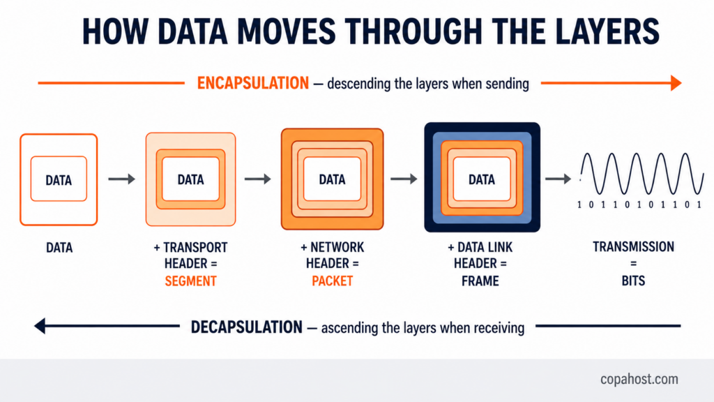
On the way down: layer 7 hands the data to layer 6, which adds its header and passes it to layer 5, and so on until layer 1 transmits the bits.
On the way up: the destination does the reverse — each layer strips its corresponding header and passes the contents upward, until the application receives the original data.
The elegance of the model is here: each layer at the destination logically converses with the same layer at the origin, ignoring everything happening beneath it.
OSI model vs TCP/IP model
This is the comparison that causes the most confusion, and the short answer is: OSI is the theoretical model, TCP/IP is what actually runs the internet.
TCP/IP came first, with a practical goal, and groups into four layers what OSI separates into seven.

| OSI model | TCP/IP model |
|---|---|
| 7 — Application 6 — Presentation 5 — Session | Application |
| 4 — Transport | Transport |
| 3 — Network | Internet |
| 2 — Data Link 1 — Physical | Network Access |
The underlying differences:
| OSI | TCP/IP | |
|---|---|---|
| Layers | 7 | 4 |
| Origin | ISO, 1984 | ARPANET, 1970s |
| Nature | Theoretical reference model | Protocol suite in active use |
| Approach | Model defined first, then protocols | Protocols came first |
| Used today for | Teaching and diagnosis | The internet’s actual implementation |
Why learn both? Because everyday vocabulary mixes them. Nobody says “internet layer firewall” — they say “layer 3”, which is OSI language, even when describing a TCP/IP network.
How to memorise the seven layers
Mnemonics are the classic approach. Top to bottom, the best known is:
All People Seem To Need Data Processing
(Application, Presentation, Session, Transport, Network, Data Link, Physical)
Bottom to top:
Please Do Not Throw Sausage Pizza Away
(Physical, Data Link, Network, Transport, Session, Presentation, Application)
Where each technology operates
This is where the model stops being theory and becomes a tool — it’s what lets you say precisely what each piece of equipment does.
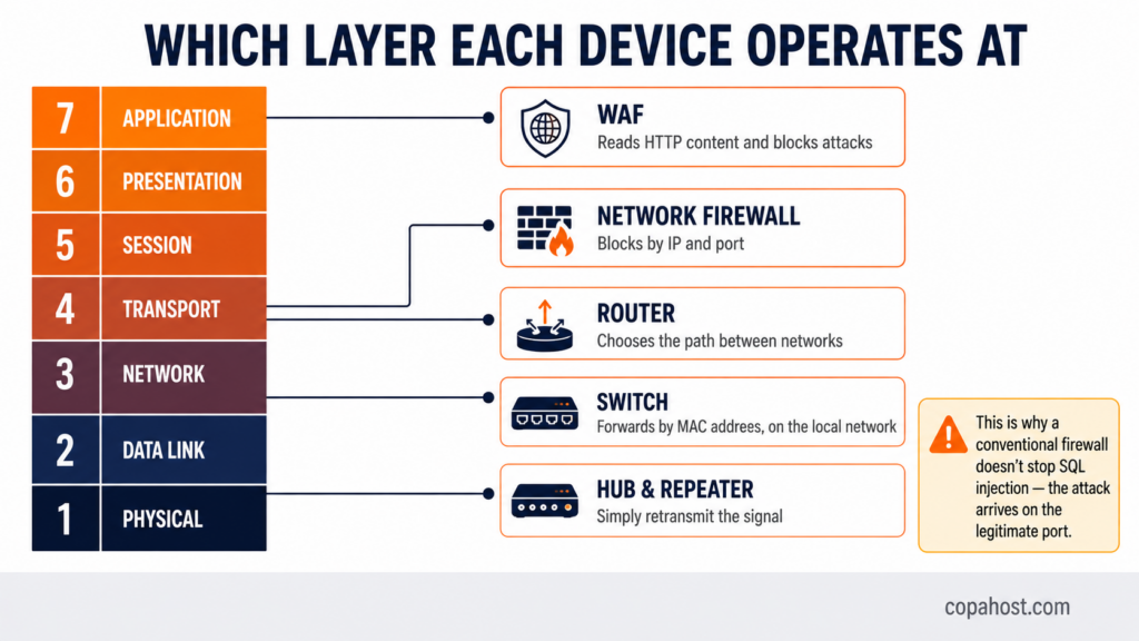
Layer 1: hubs and repeaters. They retransmit the signal without understanding anything about its contents.
Layer 2: switches. They forward frames based on MAC address, within the local network.
Layer 3: routers. They decide which path a packet takes between different networks.
Layers 3 and 4: network firewalls. They block by IP address and port — they see where traffic comes from and where it’s going, but not what it contains.
Layer 7: a WAF, or web application firewall. It reads the content of the HTTP request and blocks attack patterns like SQL injection. That distinction explains why a conventional firewall doesn’t protect a website: the attack arrives on the legitimate port.
Load balancers come in two varieties: layer 4 balancers distribute by IP and port; layer 7 balancers decide based on the request’s content, such as the URL or headers.
Why the OSI model still matters
It’s fair to ask why you’d study a model nobody implements. Three reasons:
It’s the standard language of diagnosis. When a site won’t load, the professional question is “which layer is the problem in?”. If ping responds, layers 1 to 3 work. If port 443 accepts a connection, layer 4 works. If the browser returns a 500, the problem is at layer 7. That turns “the site is down” into a structured investigation.
It defines the industry’s vocabulary. Layer 7 firewall, layer 4 load balancer, layer 3 switch — these terms appear in documentation, contracts and technical specifications every day.
It’s the basis of certifications and teaching. CCNA, CompTIA Network+ and practically every networking course starts here.
From the fibre to the application firewall: Copahost runs LiteSpeed servers with NVMe storage, free SSL, protection at layer 7, and support that knows which layer to look at when something breaks. Free migration from your current host.
See hosting plansFrequently asked questions
What is the OSI model?
It’s a reference model published by the ISO in 1984 that divides network communication into seven layers, from the physical transmission of bits to the application the user sees. Each layer has a specific responsibility, offers a service to the layer above, and consumes the service of the layer below.
What are the 7 layers of the OSI model?
Bottom to top: Physical (1), Data Link (2), Network (3), Transport (4), Session (5), Presentation (6) and Application (7). Layer 1 transmits bits across the physical medium and layer 7 is the interface with applications.
What does OSI stand for?
Open Systems Interconnection. The name reflects the original goal: allowing systems from different manufacturers to communicate, at a time when every vendor had its own proprietary network architecture.
What is the difference between the OSI model and TCP/IP?
OSI is a theoretical reference model with seven layers, created by the ISO. TCP/IP is the protocol suite that actually runs the internet, organised into four layers. TCP/IP groups OSI’s layers 5, 6 and 7 into a single Application layer, and layers 1 and 2 into Network Access.
Why does the OSI model matter if nobody uses it?
Because it’s the standard language for describing and diagnosing networks. Terms like “layer 7 firewall” and “layer 4 load balancer” come from it, and structured troubleshooting — checking whether the failure is at layer 3, 4 or 7 — is how networks are professionally investigated.
Which OSI layer does the IP protocol work at?
Layer 3, the Network layer. It handles logical addressing and routing, deciding which path packets take between different networks.
Which layer do TCP and UDP work at?
Layer 4, Transport. It guarantees end-to-end delivery between the two machines and manages ports. TCP provides reliable delivery with acknowledgement and retransmission; UDP is faster and confirms nothing.
Which OSI layer is the MAC address at?
Layer 2, Data Link. The MAC address physically identifies each network card and is used for communication between directly connected devices on the same local network. The IP address, at layer 3, enables communication between different networks.
Which layer does a firewall operate at?
It depends on the type. A traditional network firewall operates at layers 3 and 4, deciding by IP address and port. A web application firewall (WAF) operates at layer 7, analysing the content of the HTTP request. That’s why a conventional firewall doesn’t protect against attacks like SQL injection, which arrive on the legitimate port.
What is encapsulation in the OSI model?
It’s the process by which data gains a header at each layer it descends, like envelopes inside envelopes. At the origin, data moves from layer 7 down to layer 1, collecting headers; at the destination it moves from 1 up to 7, with each layer stripping its corresponding header.
What is the data unit at each layer?
Bit at the physical layer, frame at the data link layer, packet at the network layer, and segment at the transport layer. From layers 5 to 7, the unit is generically called data.
When was the OSI model created?
Work began in 1977 at the ISO and the model was published in 1984 as standard ISO/IEC 7498-1. It emerged to solve the incompatibility between proprietary architectures from vendors like IBM and DEC, which prevented equipment from different manufacturers communicating.
Which OSI layer is HTTP at?
Layer 7, Application. Alongside it sit the other protocols applications use directly: SMTP and IMAP for email, FTP for file transfer, DNS for name resolution, and SSH for remote access.
See also
For the port numbers of layer 4, see port 22, port 443 and DNS ports. For name resolution at layer 7, see what DNS stands for and reverse DNS lookup.
Conclusion
The OSI model is one of those ideas that won precisely by not being implemented: no modern network follows its seven layers literally, and yet every technology professional thinks in terms of them. The reason is that it solves a problem that hasn’t gone away — giving a precise name to each part of a process that, from the outside, looks like one thing. Knowing that the MAC address is layer 2 and the IP is layer 3, that a conventional firewall stops at layer 4 while a WAF reaches layer 7, changes how you diagnose a problem: instead of searching everywhere, you search one specific floor of the building.
